9 pin relay wiring diagram Control module power circuit The t-v curve for the given process is given below. what will be its
In the circuit of Fig. 7.117, find i x for t > 0. Let R 1 = R 2 = 1 kΩ
Solved 5.2.1 circuit 1-hardware 1. turn on the dc power 5v 2a mobile charger circuit diagram All universal lcd/led tv circuit diagram free download » soft4led
What is voltage to current converter (v to i converter) using op-amp
Solved (1 pkt) 14. a circuit schematic: is a graphicalTrinitron smps Wiring electro240vac to 48vdc converter circuit diagram.
Modulator tv video circuit schematic rf diagram circuits vhf oscillator signal electronic gr next hartley transistor interview capacitor tank buildIeee standard requirements for electrical control for ac high-voltage In the circuit of fig. 16.74, find i ( t ) for t > 0.Hyundai tv circuit diagram.

Example: using a t-v diagram to evaluate phases and states
Geneseo math 222 01 rl circuitsOn video how to make a adjustable boost converter 1.5v to 20v Power inverter circuit using 7473 ic12vdc battery charger circuit diagram.
220v ac to 12v dc converter circuit diagramSony kv20ts50 Transformer equivalent phasor referred parameters electrical determination transformers electricalacademia reactance induced[diagram] vehicle power diagram.

P v diagram p v diagram pressure ver ygraph
[diagram] lg 47le5400 lcd tv schematic diagramSimple 12 volt battery charger circuit diagram Samsung diagram wiring tv lcd circuit inverter a2 ln tft power manual supply diagrams skema circuiAnswered: 2. consider now the following circuit:….
Tv modulator under video modulator circuits -12839- : next.grCharging capacitor equation 12v 10a power supply circuit diagramDiagram states phases example.
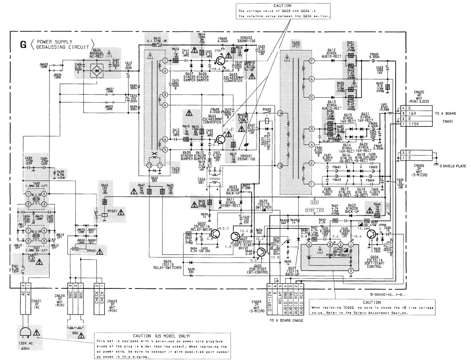
Tv circuit diagram pdf
Rl circuits circuit dt equation differential di equations geneseo dx example ri dy whyWiring diagram colour Initial v circuit brain logo 20123692 vector art at vecteezyIn the circuit of fig. 7.117, find i x for t > 0. let r 1 = r 2 = 1 kω.
Capacitor charging equation voltage matlab circuits physicsDetermination of transformer equivalent circuit parameters For the circuits shown in figures i and ii, the voltmeter reading would beAnswered: problem 1 d 22kq figure pl in the….
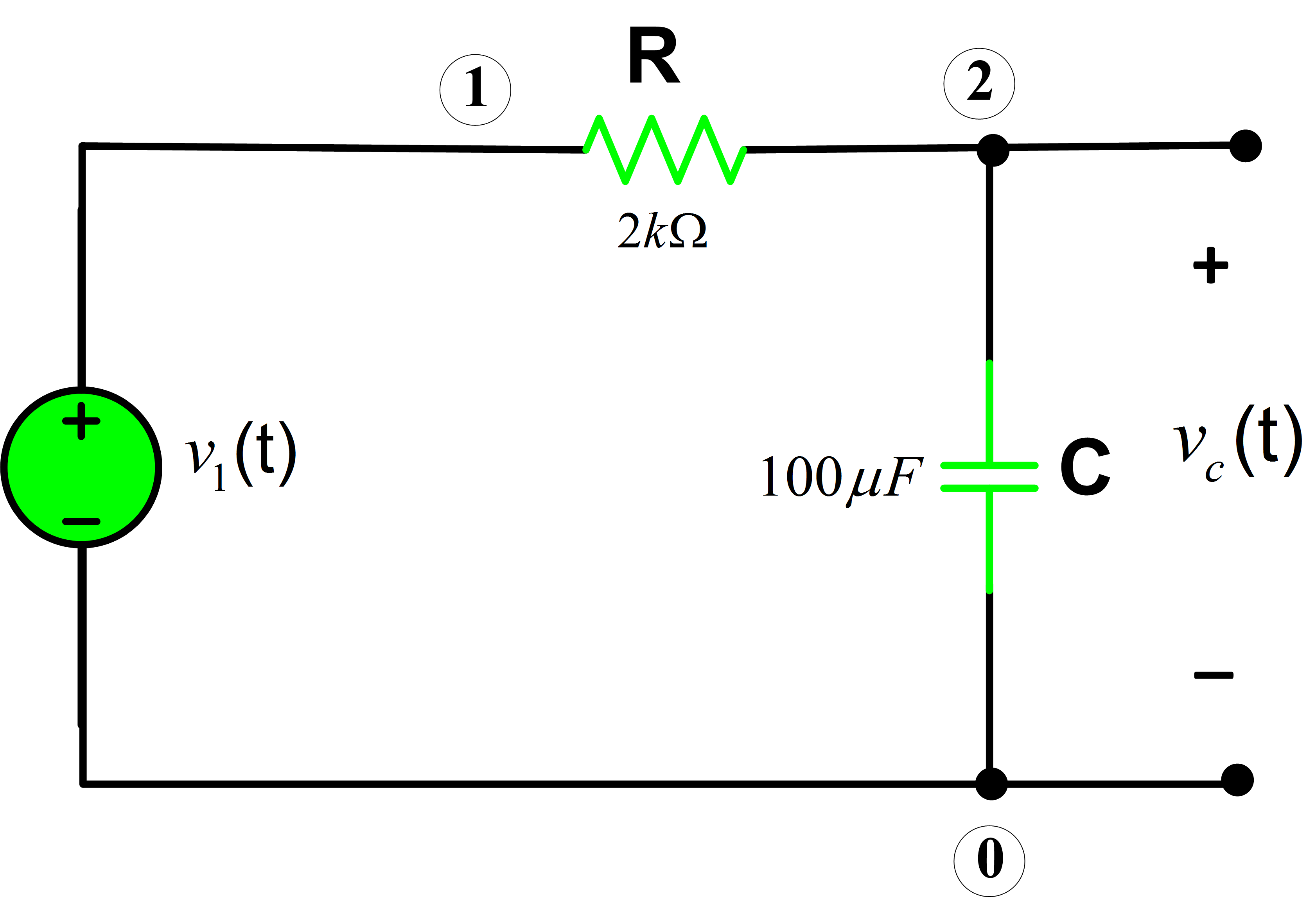

In the circuit of Fig. 7.117, find i x for t > 0. Let R 1 = R 2 = 1 kΩ

IEEE Standard Requirements for Electrical Control for AC High-Voltage

Simple 12 volt Battery Charger Circuit Diagram
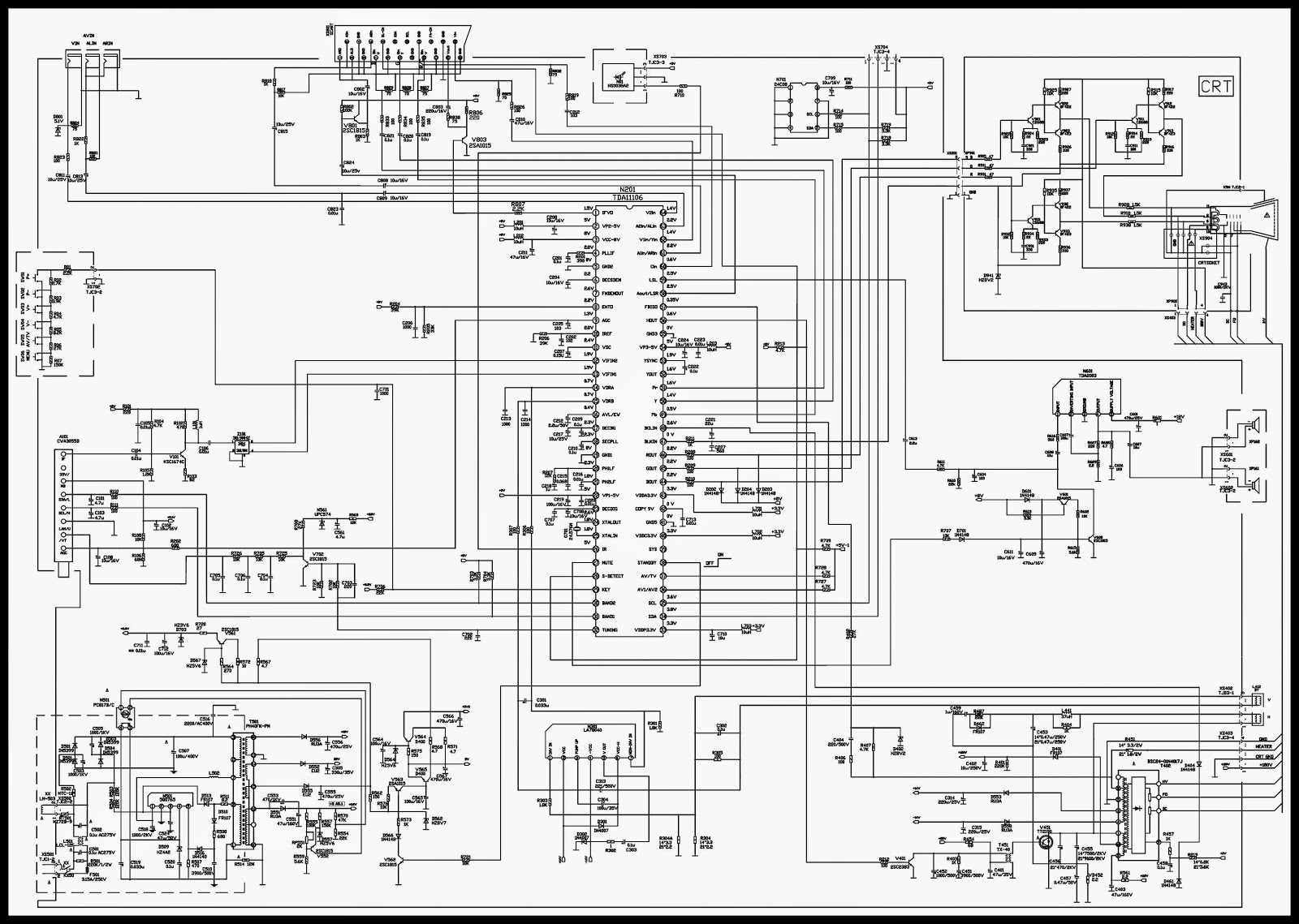
Tv Circuit Diagram Pdf
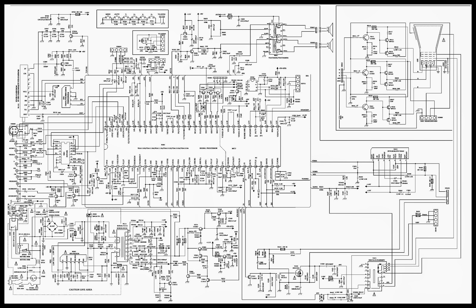
Wiring Diagram Colour

What is Voltage to Current Converter (V to I Converter) using Op-Amp
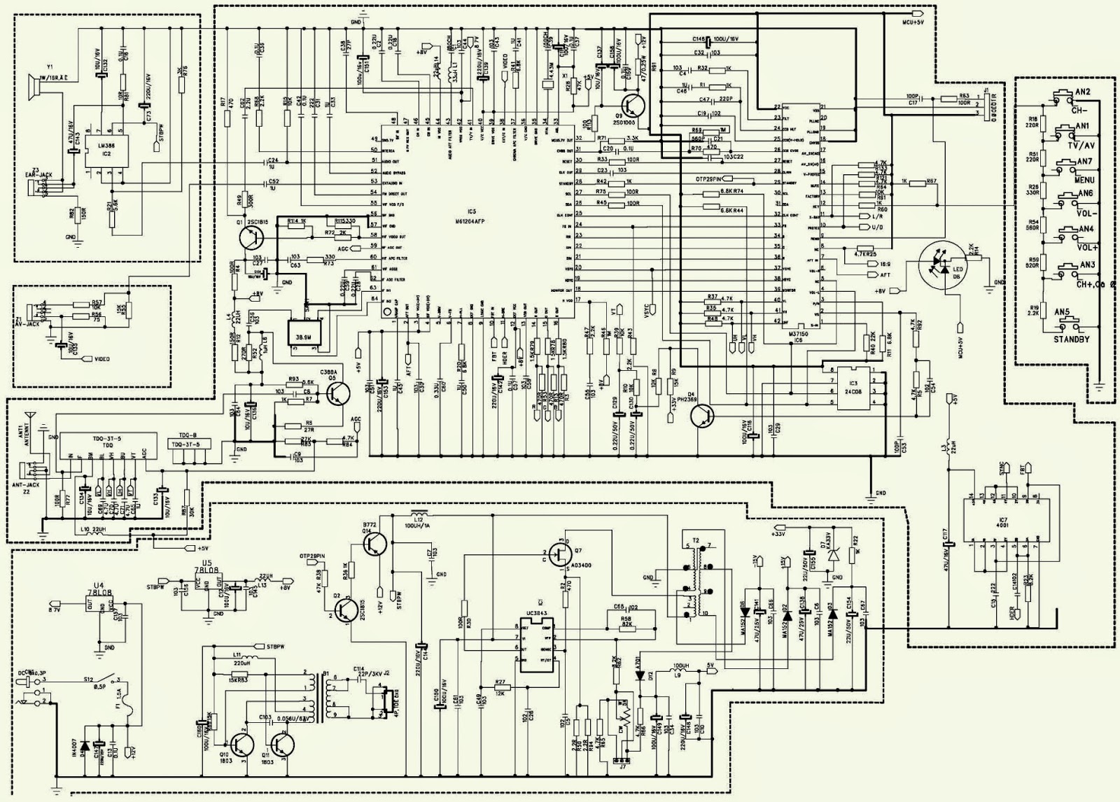
Hyundai Tv Circuit Diagram

Initial V Circuit Brain Logo 20123692 Vector Art at Vecteezy
